Help
How do I work with Teknow?
Here you can read how to draw your workpiece in the teknow Designer or work with a project if you want to produce a more extensive construction. We explain the wizard that helps you adhere to the design rules and how you can build on previous work by other users by searching for and copying drawings.
How do I draw and order a workpiece?
How does the drawing program (CAD) work
You draw your workpiece in the teknow CAD editor. You have previously specified the manufacturing method and material in the workpiece form. These data serve as the basis for applying the manufacturing rules. When you open the CAD editor, you will see the following view:
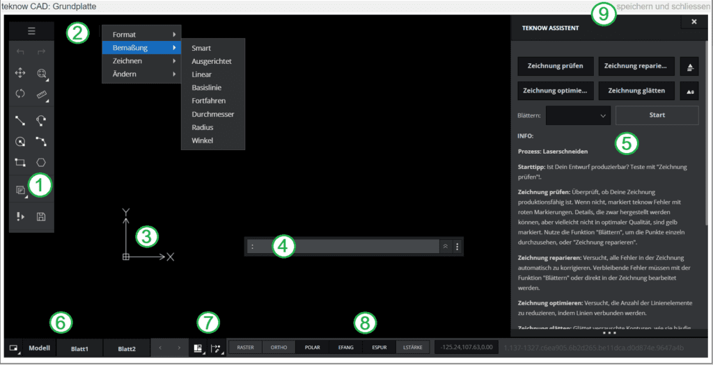
(1) The drawing palette with drawing functions
The drawing palette contains the icons of the frequently used drawing functions for quick access. If you move the mouse over the symbols, the name of the tool appears.
(2) The burger menu with further functions
Additional tools can be found in the drop-down menu at the top of the toolbar. It is opened by clicking on the three lines. The “Dimensioning” submenu is opened up as an example.
(3) The coordinate symbol is a visual reference in the drawing. It is displayed in the origin of coordinates if this is in the visible part of the graphics area, otherwise in the lower left corner of the graphics area. The coordinate symbol shows the position of the axes of the coordinate system.
(4) The command line, it allows:
-Call commands
-Select command options
-Select points and values
-confirm a selection or command execution
– Receive feedback, notices or warnings.
Clicking on the double arrow on the right of the command window shows a history of the commands entered. You can move the command window on the drawing area at the three points on the far right
The status bar is located at the bottom of the program window. It contains the following blocks:
(6) The sheet register is located on the left in the status bar. The tabs show the drawing as a model and as layouts on sheets. The model is the area in which you draw and construct. A drawing has only one model. Sheets are layouts for printouts and contain views of the model, such as overview views or details, as well as additional elements such as drawing frames and legends (which are not part of the model). You can create numerous sheets. With the sheet manager (symbol on the far left) you can add, copy, delete, name and rename sheets.
(7) Palettes and snap settings
The palettes appear on the right edge of the drawing. Before using it, you have to minimize the wizard window, otherwise it will cover the pallet. The following pallets are available:
– Properties Allows you to look up and set the properties of drawing elements. To do this, mark the drawing element with the mouse.
– Layer A drawing can consist of several layers, each of which contains information of a certain category and, when placed one on top of the other, make up the entire drawing. For example, cutting lines (white) and engraving lines (yellow) are arranged on different layers. The wizard also moves drawing elements that it considers faulty to a backup layer (magenta). In the layer palette you can manage the layers, such as switching between visible and invisible.
The snap functions are used to determine certain marked points of drawing elements such as end points or intersections of lines or centers of circles. They are used for commands that require a point to be specified (e.g. line or circle). If you approach a snapable point with the mouse, it will be marked in red. By clicking with the left mouse button, the exact point is snaped and thus, for example, the starting point of a new line.
(8) At drawing options you will find tools that will make the geometric construction easier for you. How you use the functions is explained under Working techniques. You can turn the following features on and off:
-Raster (grid display) The grid is a pattern of evenly spaced points to visualize proportions when drawing. You can turn the grid display off or on.
-Ortho (orthogonal mode) Restricts pointer movements to axes that are parallel to the coordinate axis. The function simplifies drawing objects with right angles.
-Polar (polar guidelines) The polar guidelines appear when the pointer is moved over an element snap point. The guidelines are then displayed starting from the element snap point. The angular gradation can be set by entering “polarang” in the command line (e.g. 45 °).
-EFang (element snap) Here you can switch the element snap functions on or off completely. Element snap (EFang) ensure precision when clicking in the graphics area. The EFang options allow you to record precise construction points of the existing geometry (such as start and end points of lines or arcs, centers of circles or arcs, intersections, plumb points, tangents, etc.).
-Etrack (element track guidelines) displays horizontal and vertical guidelines when moving the pointer over element snap points when element snap is on.
-With LWeigth (line width) you can switch between a finer and stronger representation of the lines. The line width of the elements does not change when you zoom in or out of the drawing. Line widths do not represent real units in the drawing geometry, unlike e.g. in design programs.
The current coordinates of the mouse pointer are displayed in the field to the right of the drawing options.
(9) With save and close you leave the CAD editor and return to the workpiece view, for example to receive the price for a production-ready workpiece. The CAD program automatically saves your drawing from time to time as you work. You can also save manually, for example if your internet connection is not stable, by clicking on the floppy disk symbol at the bottom of the drawing palette.
At the bottom of the wizard window, additional processing steps can be selected in addition to the manufacturing process (e.g. laser cutting), which are combined into modules. The choice depends on the manufacturing process.
The following are available for laser cutting:
“Featured holes” module: You get to the module page by selecting “Featured Holes” and then clicking “Open”.
Here you can insert tapped holes, countersinks and through holes matching the thread into your drawing. Select the type of hole in the first selection field (1). In the second field you can select the thread diameter (2). The corresponding thread, the countersink that matches the selected thread or the appropriate through hole is then created. After clicking on “Add” (4) you enter the coordinates in the command line as usual, or you can catch a point in the drawing.
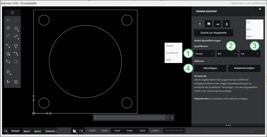
If the thread diameter cannot be produced for your sheet metal thickness, the wizard will output an error. In this case you can change the sheet metal thickness or adjust the thread diameter. The third field (3) enables further correction options: “Cut” is preset, which means that the core hole is cut with the laser as standard. In the case of small holes in certain materials, the laser-cut core hole is unsuitable for thread cutting; the wizard shows an error. Here you can try to drill the core hole by selecting “Drill”. This is a bit more expensive because it is handcrafted. If the thread cannot be produced even then, there is a further option “Mark”: then a marking cross is created as laser inscription at the point of the hole. You can then make the thread yourself at the marked position, for example with threads below M3, which we do not offer.
In the case of the countersink, the wizard outputs an error if the countersink is deeper than the sheet metal thickness.
For laser cutting, further tool modules for bending and a multi-part mode (so that you no longer need a drawing for each part) are in preparation.
How does the drawing program work?
How do I work with teknow?
To view and edit your personal data, click on “My data” (17) in the menu bar at the top right under “my teknow”. The following view opens:
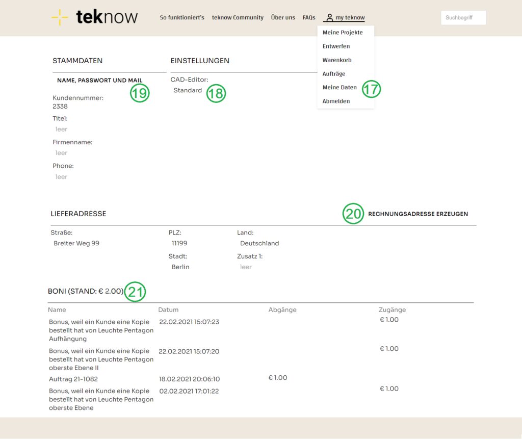
You can choose between two versions of the teknow drawing program (18). A standard version with common functions is preset. If you want an extended range of functions, you can select “advanced”.
Last name, first name, email address, login, password and language can be changed after clicking on (19).
The billing address as it appears on the invoice is transferred to the shopping cart as a default setting when an order is placed and can be changed there for each order if necessary. The data preset at this point are retained. It is only necessary to enter a billing address (20) if it differs from the delivery address.
For delivery, please note: If the shipment is going to a company, please fill in the “Company name” attribute. The postal address has an “Addition 1” field, please also fill this out if necessary for delivery.
One of teknow’s main ideas is to share drawings and learn from one another. To give all users a little impetus to share drawings with others, there is a bonus system. If someone reproduces your workpiece, teknow will credit you with a bonus. The bonuses are automatically offset against the next order. Here you can find the balance of your bonuses (21): for which orders a bonus was applied, and for which of your workpieces that were reordered by other users you received a bonus for. The bonus is € 1.
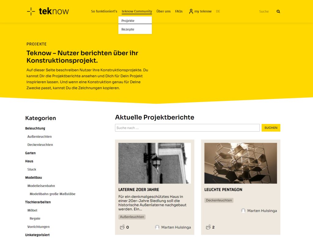
Projects
Projects
To find a suitable template for a new project, click on the “Projects” menu item under “teknow Community”. You will then see an overview of the existing construction reports from teknow users. You can limit the results using the categories or the search. Click on the picture to open the construction report. If you are logged in, you will usually find a link to the project drawings on the construction report.
To manufacture the workpieces for your project, click on the name in the tree structure (11). Then the workpiece page opens in the window on the right.
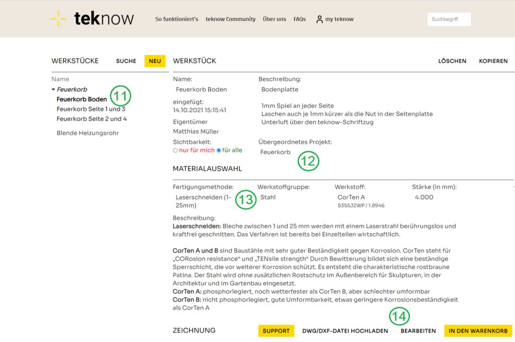
The assignment to a project is displayed (12) – here you can also assign the workpiece to another project or a folder. As usual with workpieces, you select the processing method and material (13). Clicking on “Edit” (14) opens the editor with the drawing that you have taken from your construction drawing.
The workpiece drawings may only contain a part. The teknow witard is available to you to help you comply with the production rules. For a workpiece drawn in accordance with the rules, teknow shows the price and you can order it as usual.
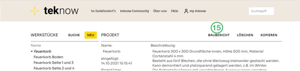
You can create and publish a construction report for your project (15) so that the report and the drawings are available for other users to replicate or as a suggestion.
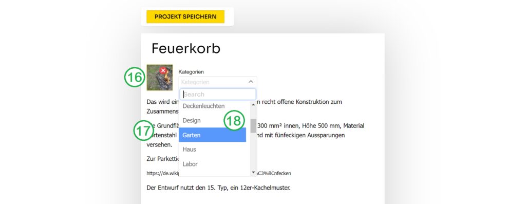
A page opens on which you can enter a title picture (16) and a summary description text (17) for a brief overview. So that other users can find the project more easily, you assign it to a category.
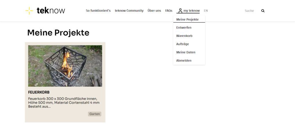
After saving, you will see your project in your personal project overview under “my teknow / projects” and under “teknow community”.
By clicking on the picture you get to the main view of the project. Here you can add additional contributions to document the progress of the project in pictures and text.