Recipes
How do I solve manufacturing tasks?
Here you will find short production recipes from the community – other users have successfully implemented these solutions.
recipes
My lathe was stored for a few years, after which the collets were partly rusted. These were stored in a wooden plate with holes, which apparently had passed on some moisture.
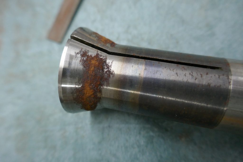
Contrary to the fear that the collets would have to go to the scrap box, they could be saved quite easily by carefully filing the rust off radially with a fine file (a bit out of focus in the background).
Then the collet looks like this. A discoloration remains, but you can no longer feel any unevenness. According to the clock, the concentricity is about 1/100. The machine is a Leinen DLZ 140.
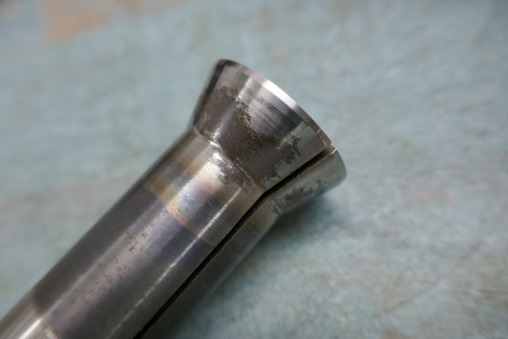
It may not always work that way, depending on where the rust goes and the quality of the material.
A device is required to set the crankpins on a model steam locomotive at an exact angle. The one I used consists of two plates, each with a central hole for a guide pin, which is received by the axle hole of the wheel and centers the wheel in the guide. Then there are two more holes that accommodate the drive or coupling pin and thus determine the angular position. The crankpins must therefore be mounted on the wheel before the wheels are pressed on. This is what a plate looks like:
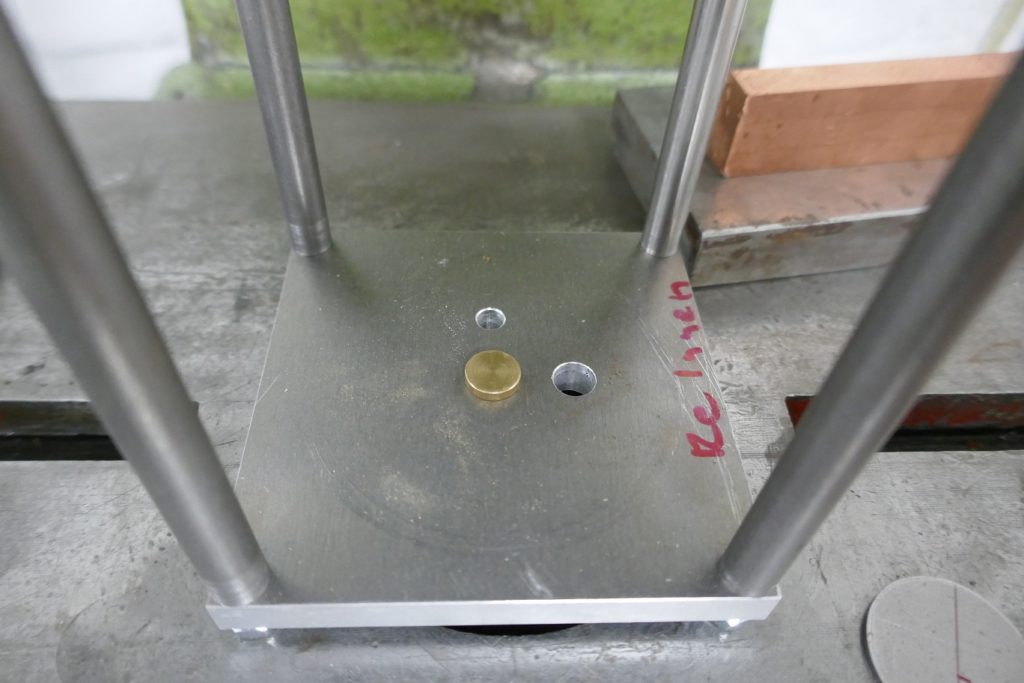
Four stretchers position the two plates in relation to one another. The upper plate is placed in such a way that the right crank runs 90 ° ahead of the left when driving forward.
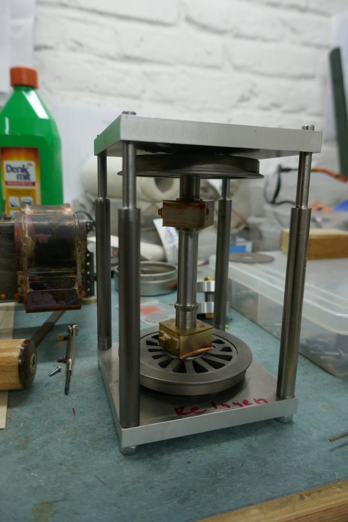
The axis in the device. In this model, the axle bearing bushes are closed and must be pushed onto the axle before being pressed on.
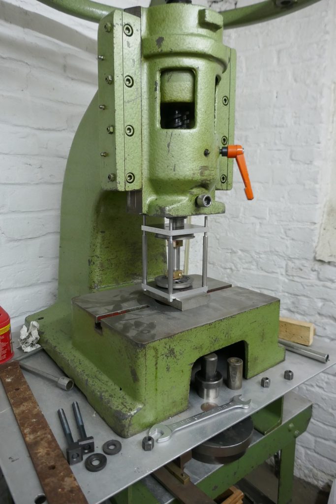
Pressing on the wheels in the screw press. The first step is to press in the angle device until the axis touches the centering pin. Then you take the axle out of the device and press the last piece on a surface. The correct distance is achieved when the axle touches down on the base, i.e. is flush with the wheel hub.
I made wheel pattern for a 1:16 scale locomotive model of the Prussian steam express train locomotive S10. The pattern for the spokes was realized as a laser part. The wheel tires and the webs of the crank axle are also laser parts.
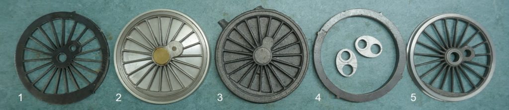
The pictures show the production sequence:
1. Lasered wheel spider for the cast model. The lintel is made on the milling machine and the spokes are then filed into shape.
2. Assembled casting model, for molding in sand.
3. Cast blank, this is shaped by turning.
4. Lasered blank for the wheel tire. This is shrunk onto the wheel center. In the middle the lasered blanks for the webs of the crank axis.
5. Fully assembled wheel with profiled running surface.
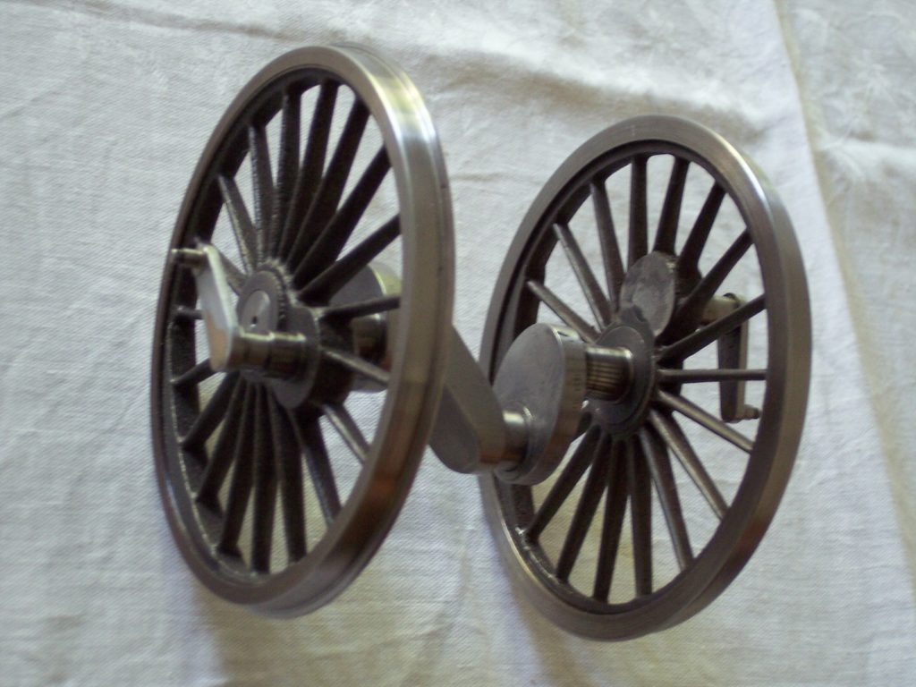
This is what the fully assembled crank axle looks like, with pressed-in drive pins and a hard-soldered counter crank.